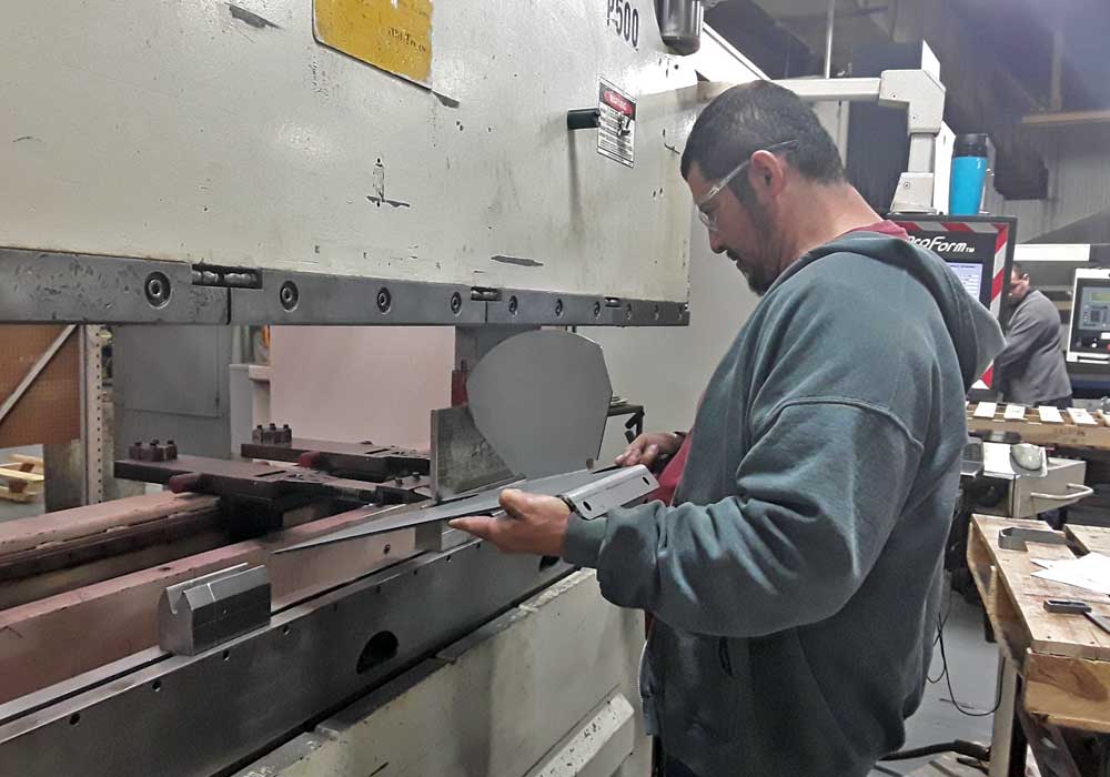
In press brake forming, a work piece is positioned over a die block while a punch presses the sheet into the die to form a shape.
Usually, bending has to overcome both tensile stresses and compressive stresses. When bending is done, the residual stresses cause the material to spring back towards its original position, so the sheet must be over-bent to achieve the proper bend angle. The amount of spring back is dependent on the material, and the type of forming.
When sheet metal is bent, it stretches in length. The bend deduction is the amount the sheet metal will stretch when bent as measured from the outside edges of the bend. The bend radius refers to the inside radius. The formed bend radius is dependent upon the dies used, the material properties, and the material thickness.
Three Types of Forming by Brake Press Operations:
Air Forming allows us to use the same die and punch to make a range of bend angles and radius’ when tolerances are wide enough to do so.
In Bottoming, the sheet is forced against the V opening in the bottom tool. U-shaped openings cannot be used. This is a little more costly than Air Forming in that each tool is for a particular angle and radius.
Coining, the top tool forces the material into the bottom die with 5 to 30 times the force of air bending, causing permanent deformation through the sheet. There is little, if any, spring back. Coining can produce an inside radius smaller than the material thickness. While coining can attain high precision and repeatability, it also means higher cost so is not used as often.
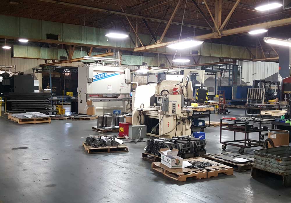
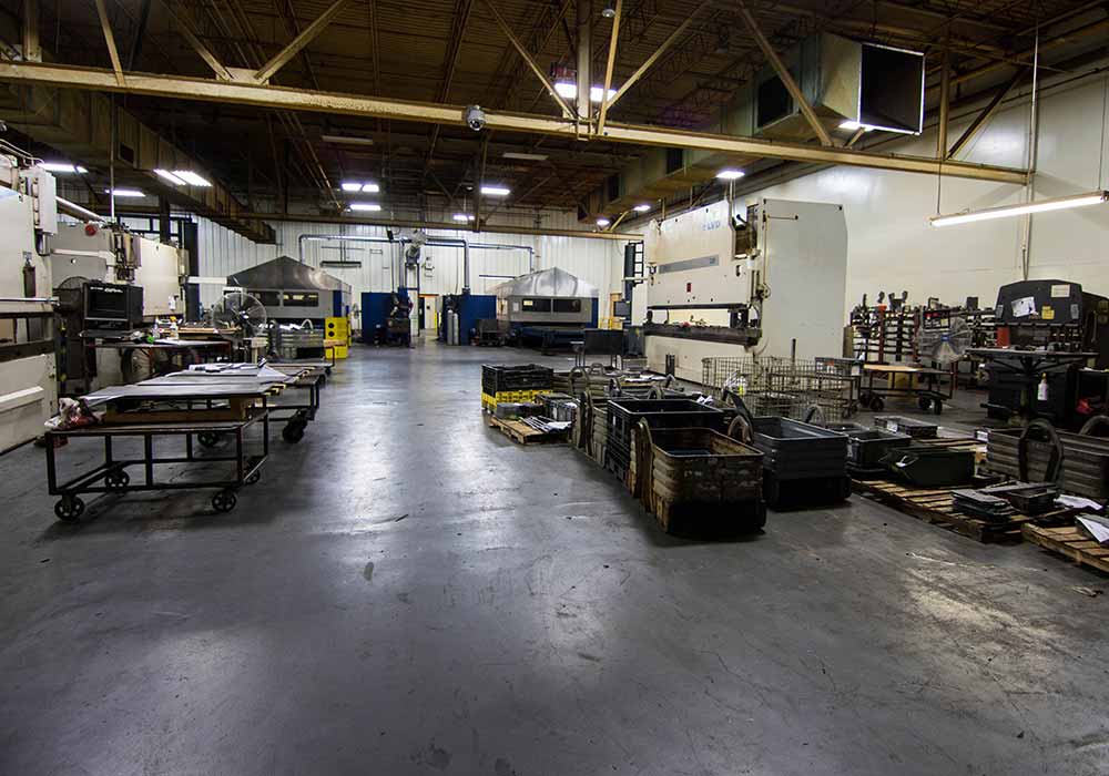
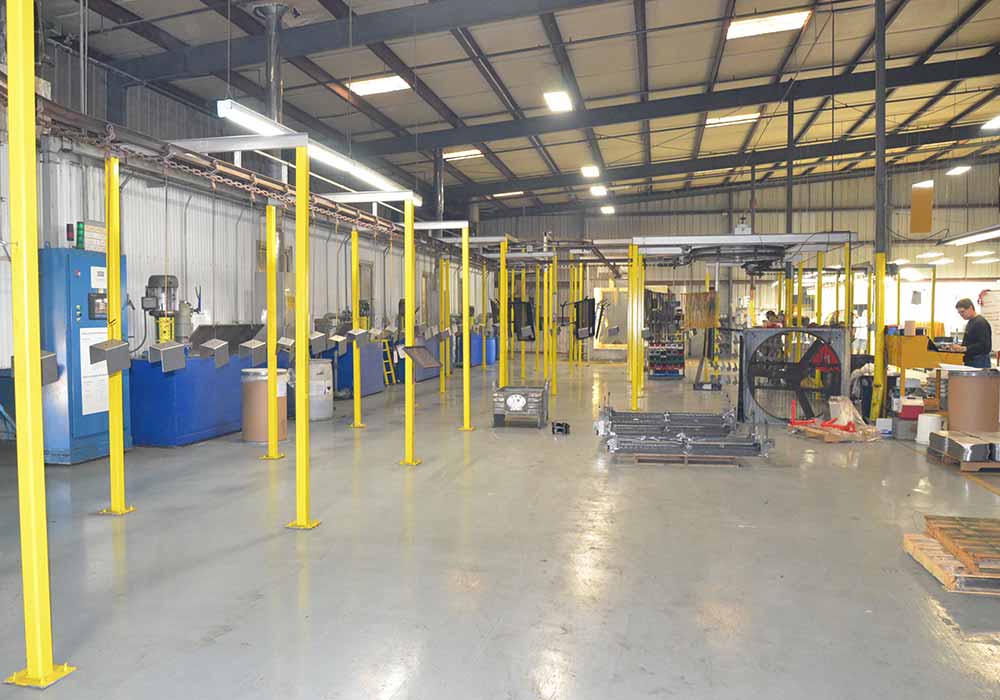
Brake Press Area
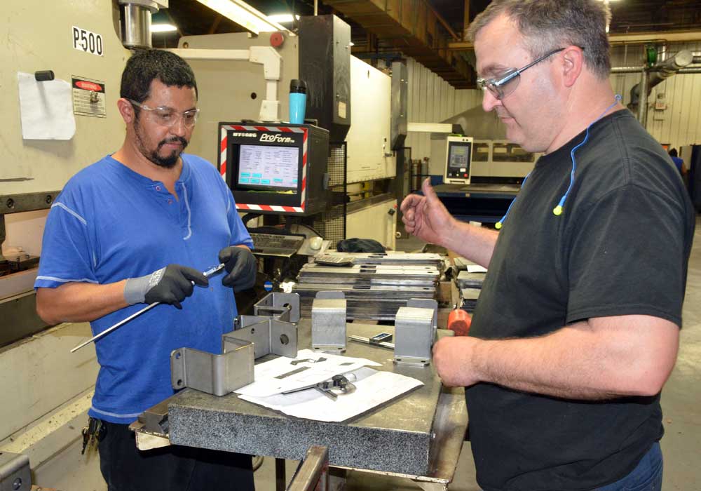
Brake Press
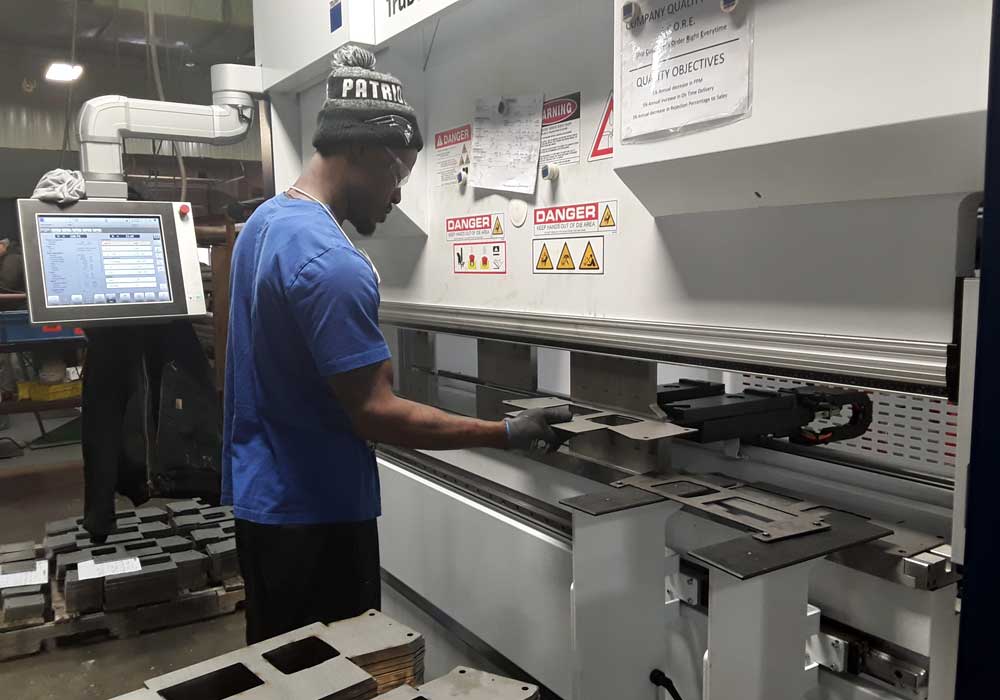
Brake Press Production
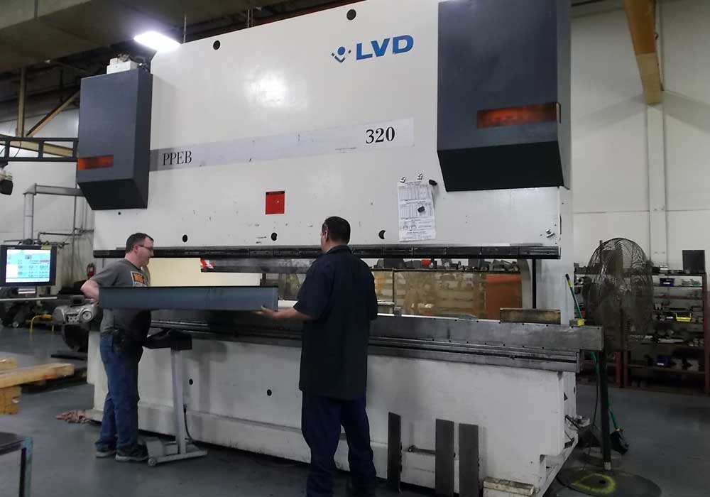
LVD Brake Press
PEM Inserting
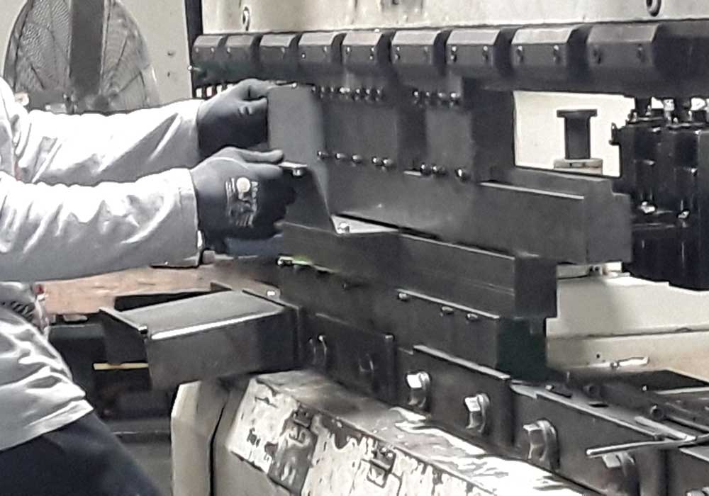
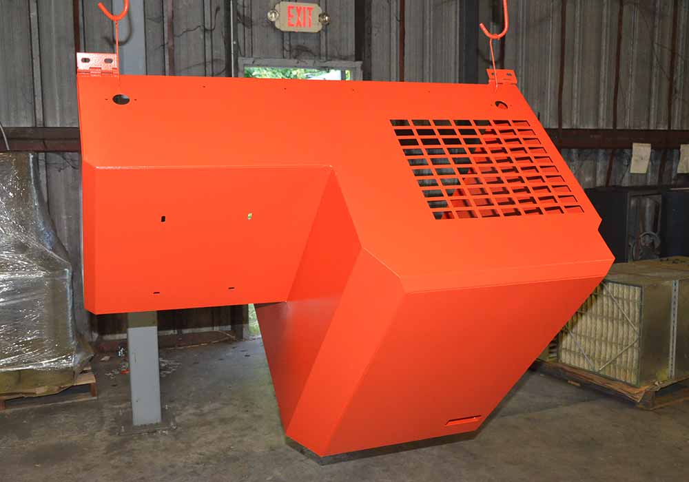
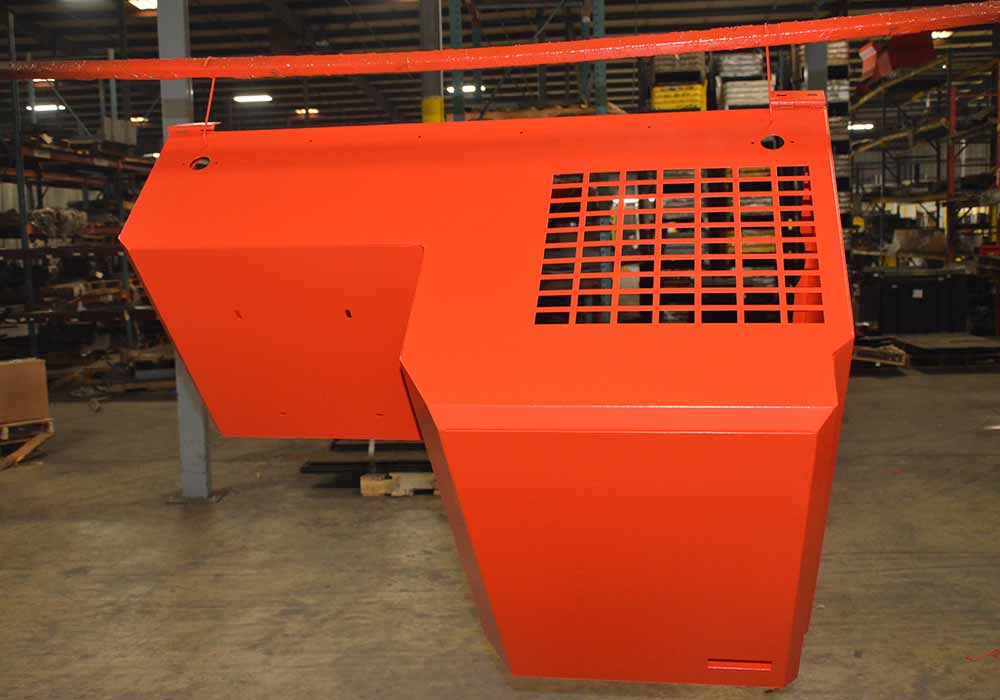
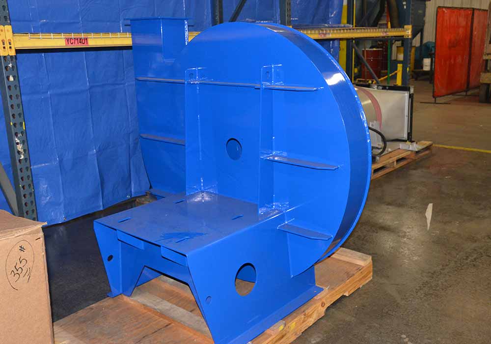
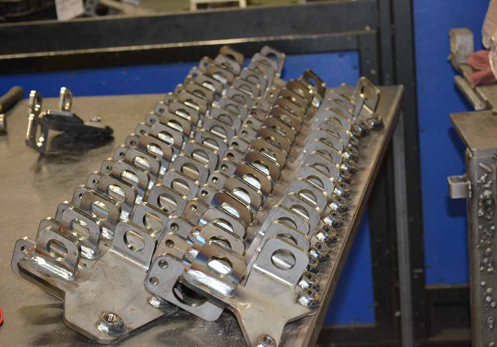
Forming Metal
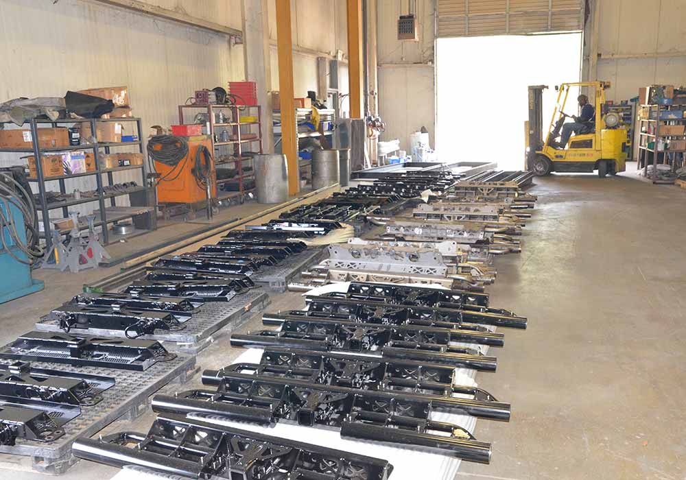
Production Forming
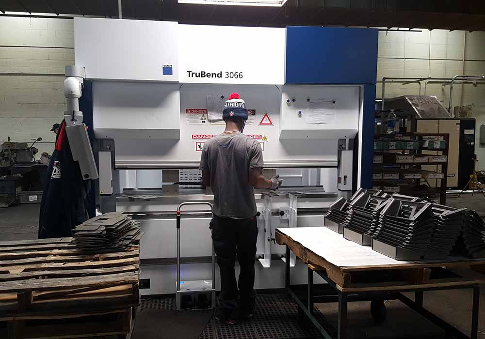
Trubend Production
Brake Press Area
Brake Press Area
Production Forming
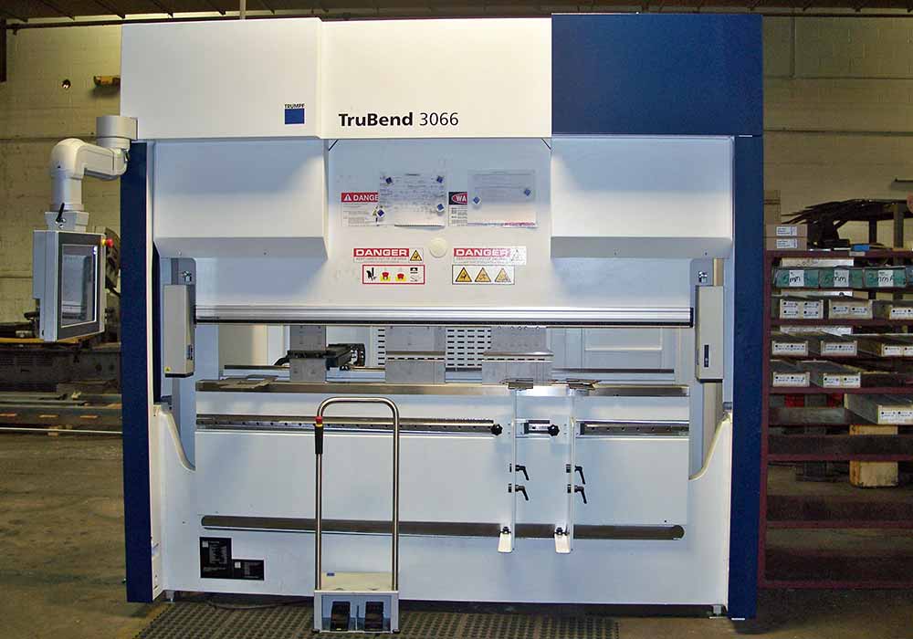
TruBend
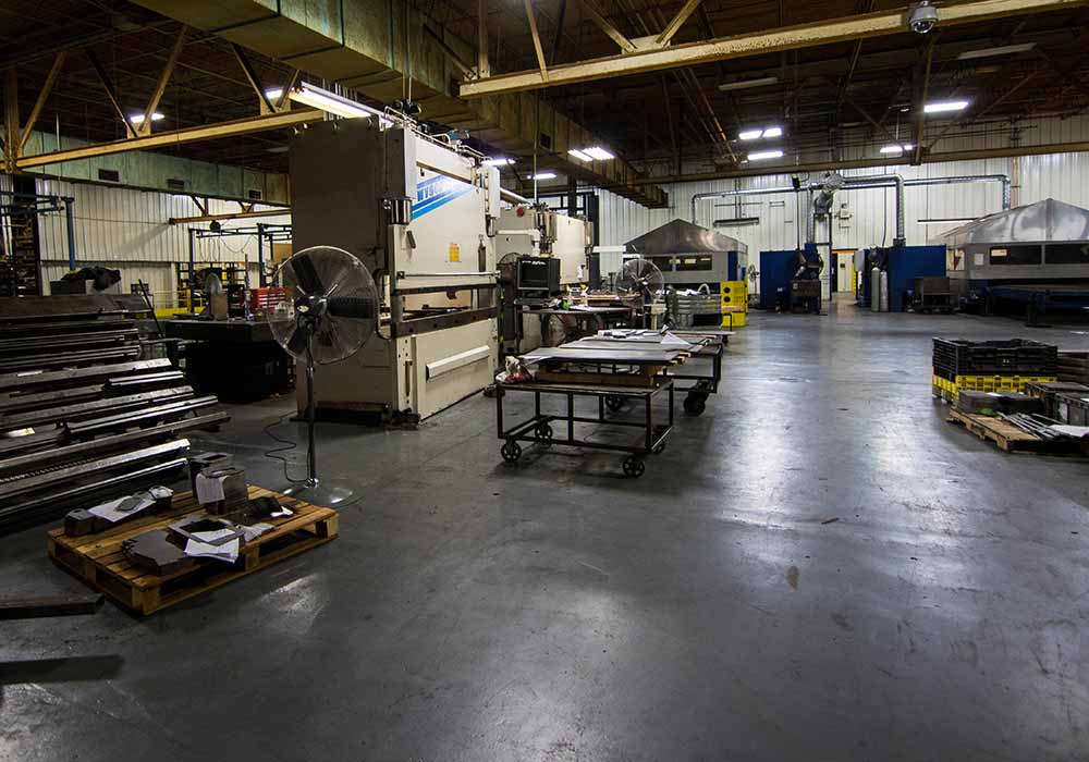
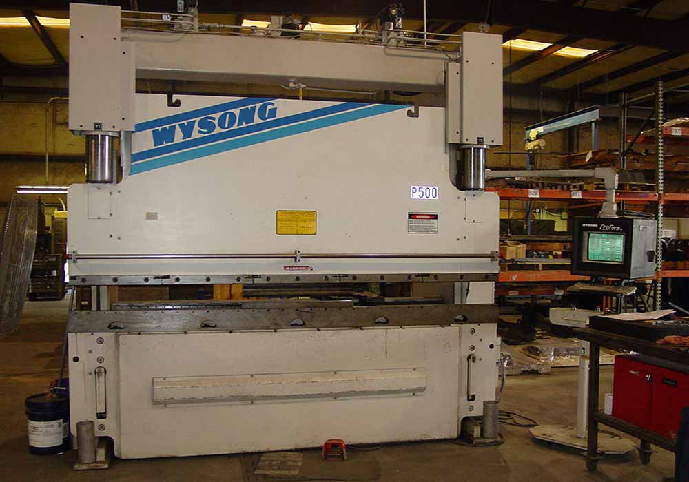
Wysong Brake Press
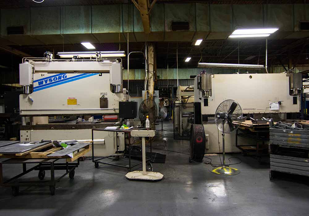
Wysong And Hurco
Wysong Brake Press
In press brake forming, a work piece is positioned over a die block while a punch presses the sheet into the die to form a shape.
Usually, bending has to overcome both tensile stresses and compressive stresses. When bending is done, the residual stresses cause the material to spring back towards its original position, so the sheet must be over-bent to achieve the proper bend angle. The amount of spring back is dependent on the material, and the type of forming.
When sheet metal is bent, it stretches in length. The bend deduction is the amount the sheet metal will stretch when bent as measured from the outside edges of the bend. The bend radius refers to the inside radius. The formed bend radius is dependent upon the dies used, the material properties, and the material thickness.
Three Types of Forming by Brake Press Operations:
Air Forming allows us to use the same die and punch to make a range of bend angles and radius’ when tolerances are wide enough to do so.
In Bottoming, the sheet is forced against the V opening in the bottom tool. U-shaped openings cannot be used. This is a little more costly than Air Forming in that each tool is for a particular angle and radius.
Coining, the top tool forces the material into the bottom die with 5 to 30 times the force of air bending, causing permanent deformation through the sheet. There is little, if any, spring back. Coining can produce an inside radius smaller than the material thickness. While coining can attain high precision and repeatability, it also means higher cost so is not used as often.
Brake Press Area
Brake Press
Brake Press Production
LVD Brake Press
PEM Inserting
Forming Metal
Production Forming
Trubend Production
Brake Press Area
Brake Press Area
Production Forming
TruBend
Wysong Brake Press
Wysong And Hurco
Wysong Brake Press
Southeastern Tool and Die offers both wet paint and powder coating. We have both a conveyor and a batch oven and can provide multiple color changes. We currently use Valspar, Sherwin Williams, and Akzo Nobel powder paint.
We are certified for military CARC (Chemical Agent Resistant Coating) wet, with or without a powder coat primer. We have Green, Tan, and Black CARC for all of our military customers. We utilize gas heat lamps for force curing of the CARC and wet coating for shorter curing times.
We Offer Four Types of Part Finishing
Wet Spray Paint
Powder Coating
Plating
for Military Customers, CARC paint
1. Wet Paint
Wet paint is a painting technique where a device sprays a coating (paint, ink, varnish, etc.) through the air onto a surface. This process requires extra care in the prep of the parts being painted. A ‘TAC” cloth is used to wipe the parts down to remove any trash or deposits left behind after washing the parts. The parts require a flash time to start the curing process and can take up to a couple of hours before dry enough to touch. Handling take more time 5 hours depending on the ambient temperature of the surrounding room.
2. Powder Coating
The invention of powder coating and the powder coating oven emerged as a response to the many issues that existed in the liquid finishing industry. The main issues were that the finishes did not last long enough, products contained a released volatile organic compounds when resins were being applied and the high costs associated with maintaining the proper safety equipment and pollution control units that were requires for applying traditional liquid finishes. In the 1940’s, the European finishing and coating industries were under tremendous pressure to find a more environmentally friendly way to process and dry coatings. The current method of coating was flame spraying, which utilizes combustible gasses to create the energy necessary to melt the coating material.
It was in the late 1940’s that Dr. Erwin Gemmer developed a way to fluidize the bed application for thermoplastic resins on metal as a more efficient alternative to flame spraying.
Powder Coating ProcessThe new powder coating method could be applied to new or used parts after they have been degreased and chemically cleaned to provide a proper surface. The coated part is then placed in a powder coating oven for 2-4 hours to complete the process.
Over the next 40 years, major improvements in coating and application processes and the efficiency of the powder coating oven brought the industry huge amounts of growth. By the 1980’s, the process and the powder coating oven had gained enormous popularity as breakthrough advances in resins and powder coating oven procedures had decreased waste, increased efficiency and lowered processing costs.
Today this coating can be applied and dried in a powder coating oven in as little as an hour. A standard powder coating oven on the market today can dry a coating resin in 15 minutes. These technological improvements continue to be driven by the automotive, aerospace, appliance and general industrial markets.
3. Plating
Metal plating provides many benefits to products made from metal and other materials. Plating is a manufacturing process in which a thin layer of metal coats a substrate. This can be achieved through electroplating, which requires an electric current, or through electroless plating, which is in autocatalytic chemical process. In either case, the technique results in one or several of the following benefits:
Improved corrosion resistance
Decorative appeal
Increased solderability
Enhanced strength
Reduced friction
Altered conductivity
Enhanced paint adhesion
Increased magnetism
4. CARC Painting
CARC (Chemical Agent Resistant Coating) is a paint commonly applied to military vehicles and equipment to provide protection against chemical and biological weapons. We offer Green, Tan, and Black CARC coatings.
The surface of the paint is engineered to be easily decontaminated after exposure to chemical warfare and biological warfare agents. The paint is also resistant to damage and removal by decontaminating solutions. Two-component systems (e.g. epoxy or polyester-based) are often employed. This coating is described in MIL-DTL-53072E.
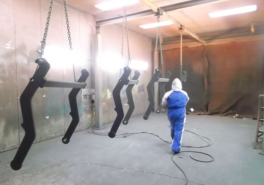
The photos demonstrate our painting capabilities and processes.
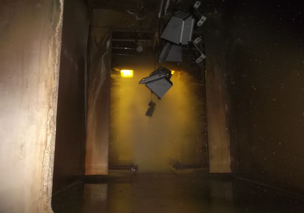
Powder Coating on the Conveyor Line
Conveyor 5 Stage Wash
Degreaser, Iron Phosphate and Sealer applied in the 5 Stage Wash
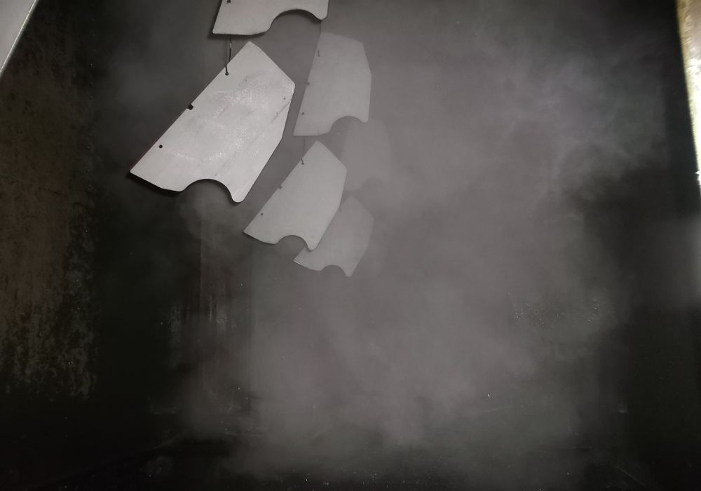
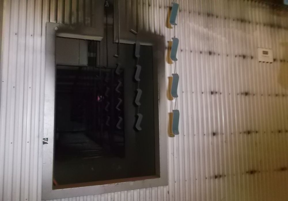
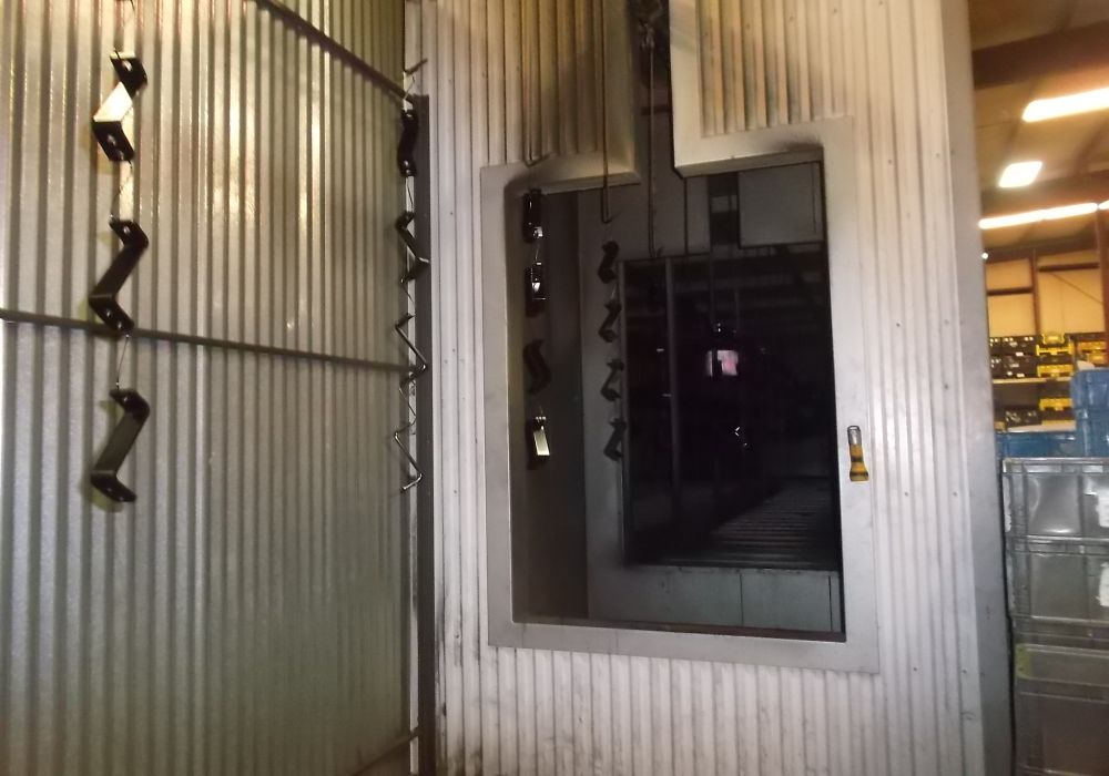
Parts going into the Cure Oven
Cured and Finished Parts
Final inspection at the Conveyor Line
Conveyor Powder Coating 2
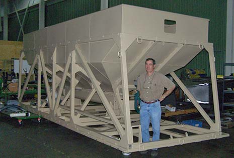
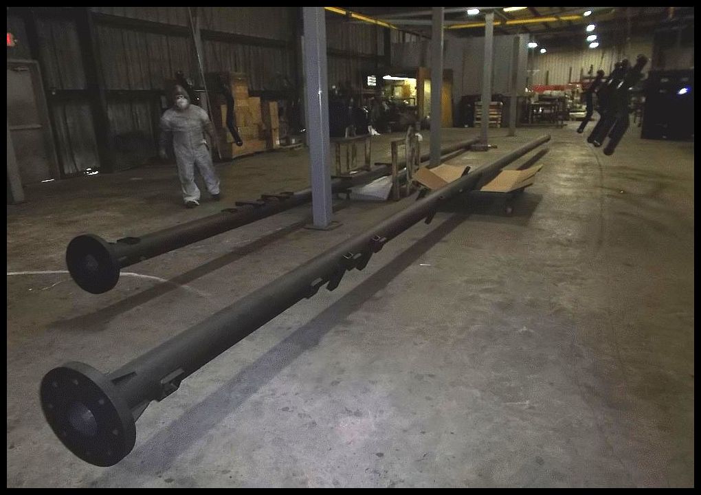
Batch Coating
Long antenna mount from Batch
Batch 1
Batch 2
Batch 3
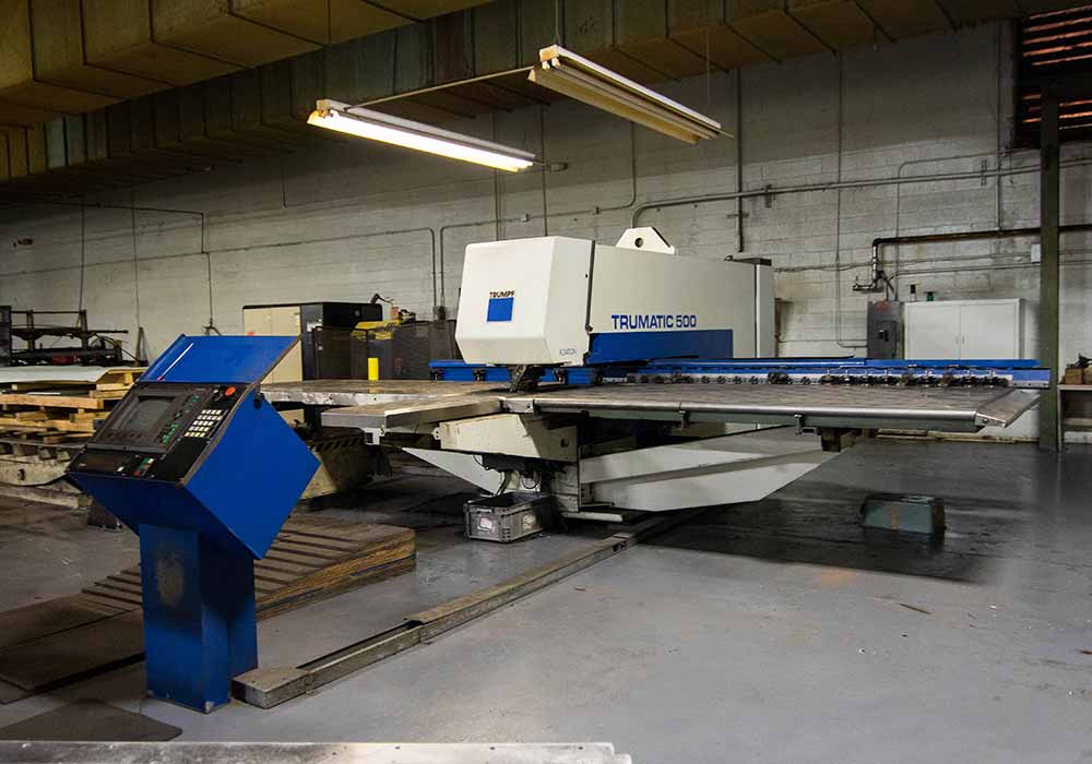
A punching machine works much like a hole punch for paper. With a paper punch, the punch presses the paper against the support of the hole punch and finally into a round opening and the scrap from the punching is collected in the hole punch container.
Machine punching works in the same way. The sheet is positioned between the punch and the die. The punch moves downward and plunges into the die. The edges of the punch and the die move past each other in parallel, cutting the sheet. Observed in detail, the punching process proceeds in four phases.
When the punch touches the sheet, the steel is deformed.
Then it is cut.
Finally, the tension within the material is so great that the sheet breaks along the contour of the cut.
The cut out piece of steel – the punching slug – is ejected downward.
When the punch moves upward it can pull the sheet with it. In that case, the stripper releases the sheet from the punch. The higher the fraction of cut on the sheet edge, the better the edge quality. For precise fits, for example, preliminary holes are punched and then the final diameter is punched out with a slightly larger tool. The fraction of cut along such an edge is then as high as 100%.
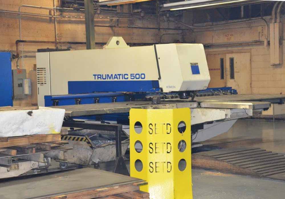
TC 500 Punch
TC Punch
TC
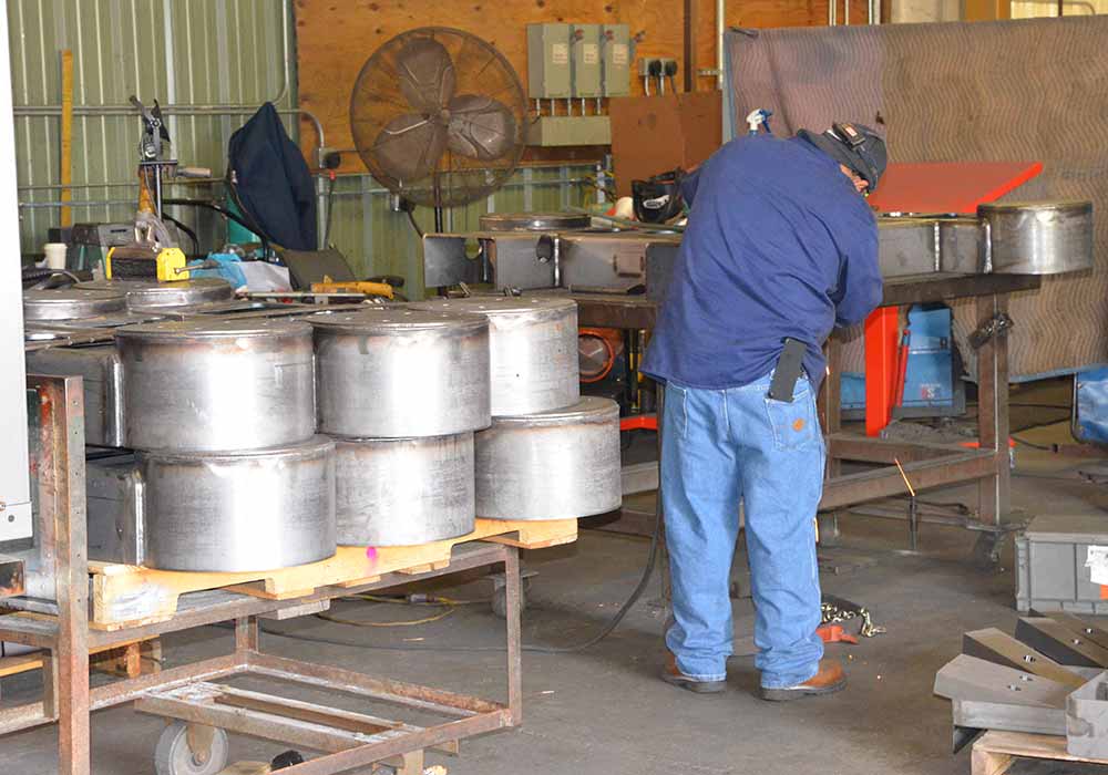
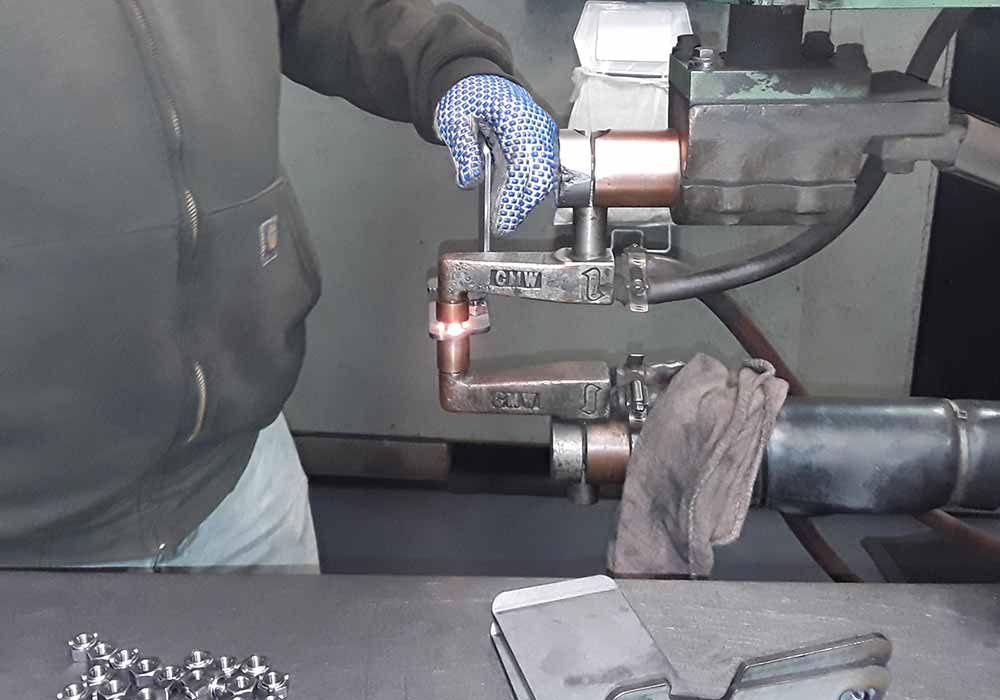
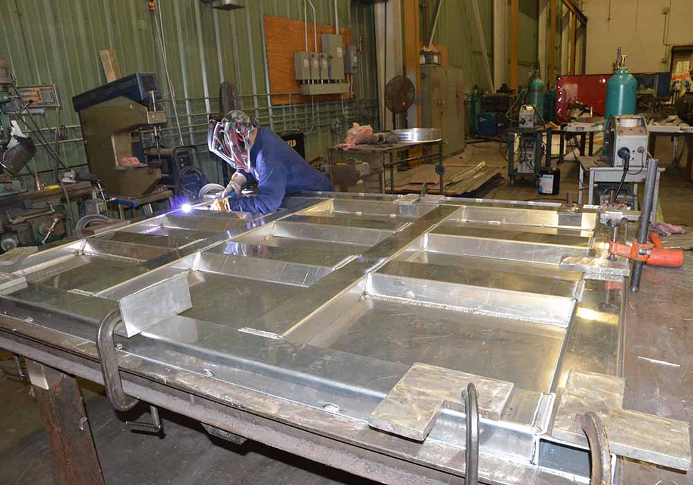
Welding is a fabrication or sculptural process that joins materials, usually metals or thermoplastics, by causing fusion, which is distinct from lower temperature metal-joining techniques such as brazing and soldering, which do not melt the base metal. In addition to melting the base metal, a filler material is typically added to the joint to form a pool of molten material (the weld pool) that cools to form a joint that is usually stronger than the base material. Pressure may also be used in conjunction with heat, or by itself, to produce a weld. Standard weld methods are GMAW (Gas Metal Arc Welding), GTAW (Gas Tungsten Arc Welding) and Spot Welding.
GMAW
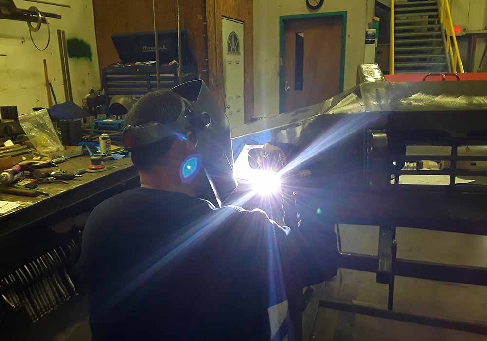
GMAW (Gas Metal Arc Welding) – commonly referred to as MIG welding - is a welding process in which an electric arc forms between a consumable wire electrode and the workpiece metal(s), which heats the workpiece metal(s), causing them to melt and join.
GTAW
GTAW (Gas Tungsten Arc Welding) – xommonly referred to as TIG welding - is an arc welding process that uses a non-consumable tungsten electrode to produce the weld.
The weld area is protected from atmospheric contamination by an inert shielding gas (argon or helium), and a filler metal is normally used, though some welds, known as autogenous welds, do not require it.
A constant-current welding power supply produces electrical energy, which is conducted across the arc through a column of highly ionized gas and metal vapors known as a plasma.
MIG Welding GMAW
Production MIG Welding
Production MIG Welding
Production MIG Welding
Production MIG Welding
Spot Welding
TIG Welding GTAW
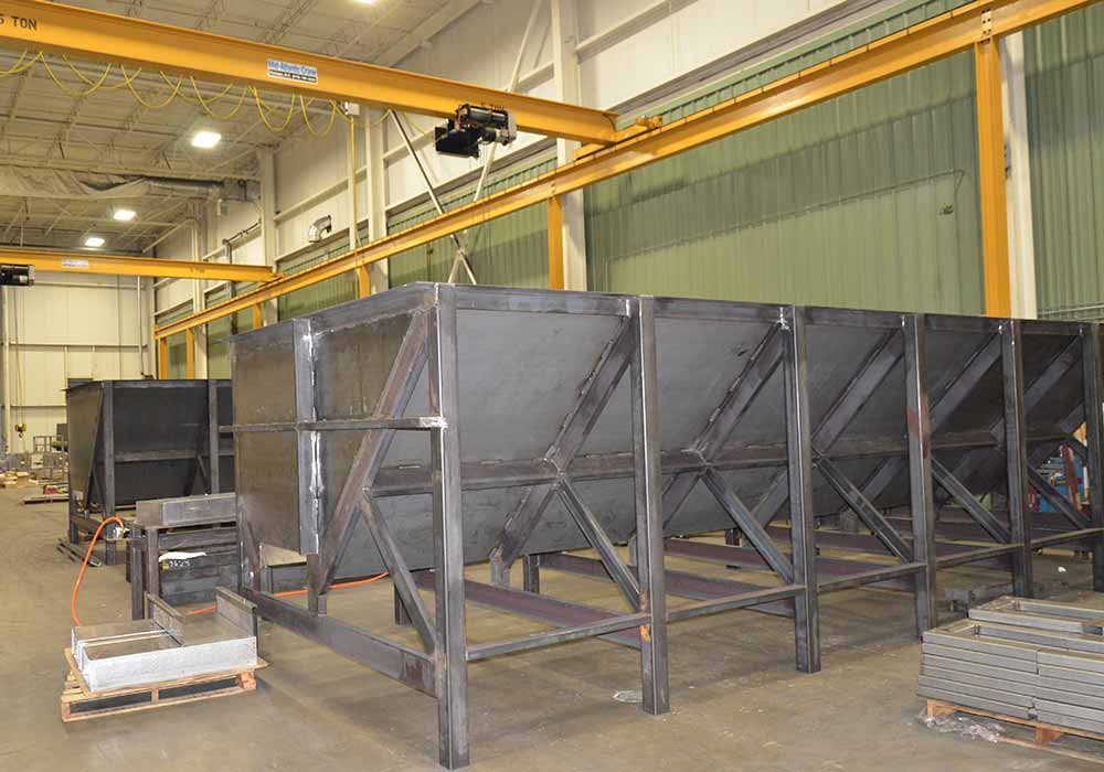
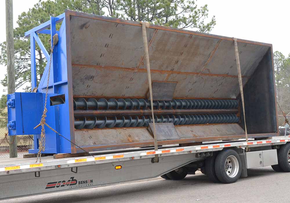
Welding Assembly
Welding Assembly
Welding Assembly
Welding Assembly
Welding Assembly
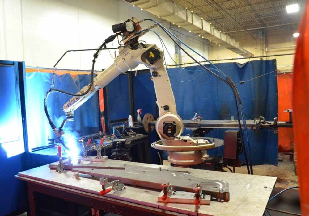
Robotic Welding
Robotic welding is the use of mechanized programmable tools (robots), which completely automate a welding process by both performing the weld and handling the part. Processes such as gas metal arc welding, while often automated, are not necessarily equivalent to robot welding, since a human operator sometimes prepares the materials to be welded. Robot welding is commonly used for resistance spot welding and arc welding in high production applications, such as the automotive industry.
Robot welding is a relatively new application of robotics, even though robots were first introduced into US industry during the 1960s. The use of robots in welding did not take off until the 1980s, when the automotive industry began using robots extensively for spot welding. Since then, both the number of robots used in industry and the number of their applications has grown greatly. In 2005, more than 120,000 robots were in use in North American industry, about half of them for welding.[1] Growth is primarily limited by high equipment costs, and the resulting restriction to high-production applications.
Robot arc welding has begun growing quickly just recently, and already it commands about 20% of industrial robot applications. The major components of arc welding robots are the manipulator or the mechanical unit and the controller, which acts as the robot's "brain". The manipulator is what makes the robot move, and the design of these systems can be categorized into several common types, such as SCARA and cartesian coordinate robot, which use different coordinate systems to direct the arms of the machine.